Circuit notes: the mid-hump overdrive
These notes record what public sources say about the classic green mid-hump overdrive pedals (the Ibanez TS808 and TS9 family), and how MidHump turns that into DSP. The manufacturer and product names appear here only to identify the reference hardware. The plugin carries none of that branding.
No proprietary plugin or firmware was inspected. Everything below comes from the sources at the end, plus standard circuit analysis.
Status of these notes
The first draft was written in a session that could not open the primary sources (ElectroSmash, GeoFex, the Yeh papers): the network policy blocked them. Its values came from search-engine summaries of those pages, from the figures quoted in issue #31, and from the author's recall of the standard schematic. In October 2026 the GeoFex article [2] and the DAFx-07 paper [3] were read directly, and the values below are marked against them. ElectroSmash [1] was still unreachable, and the input coupling capacitor is still unsourced. Check every remaining reported and inferred value against the primary sources before the effect is released.
Confidence levels used throughout:
- Documented: stated by the manufacturer, a datasheet or a cited paper.
- Reported: stated by one or more third parties (an analysis, a forum post or a measurement). Where only a summary was seen, the text says so.
- Inferred: my own reasoning from the reported facts.
- Chosen: a free modelling choice where no source gives a value.
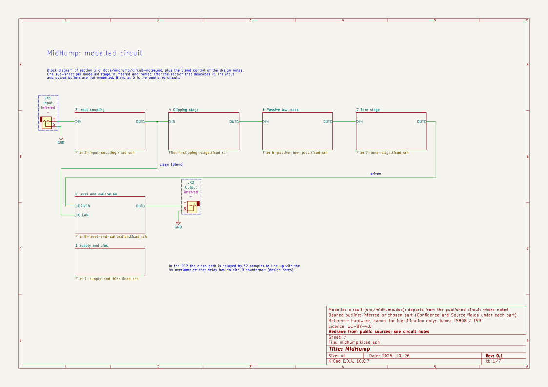
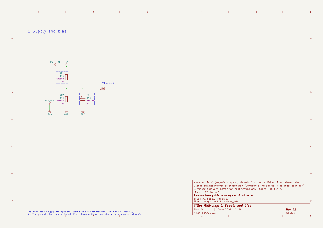
Each section with component values has a sheet of the KiCad schematic, redrawn from these notes. It is the circuit MidHump implements: where the model departs from the published circuit (the tone stage, Blend, the Level range), the sheet draws the model and says so. Dashed outlines mark inferred and chosen parts, and designators with an X (RX3, UX1 …) mark parts the notes do not name.
1. Controls and interface
The pedal has three controls: Drive (distortion), Tone and Level (issue #31, sources [1] and [2]). MidHump adds a fourth, Blend, which the pedal does not have (see the design notes). At Blend 0 the plugin is the model described here.
2. Block diagram
in → input buffer → clipping stage ┬→ 723 Hz passive low-pass → active tone stage → Level → output buffer
                                   └ op-amp with diodes in the feedback loop
Input and output buffers are not modelled (chosen). They are emitter followers whose job is impedance matching, so a digital model has no use for them.
The schematic's root sheet is this block diagram plus Blend, with one sub-sheet per stage. Sheet 1 holds a 9 V supply and a bias rail, both chosen, so the op-amp stages can be wired.
3. Input coupling
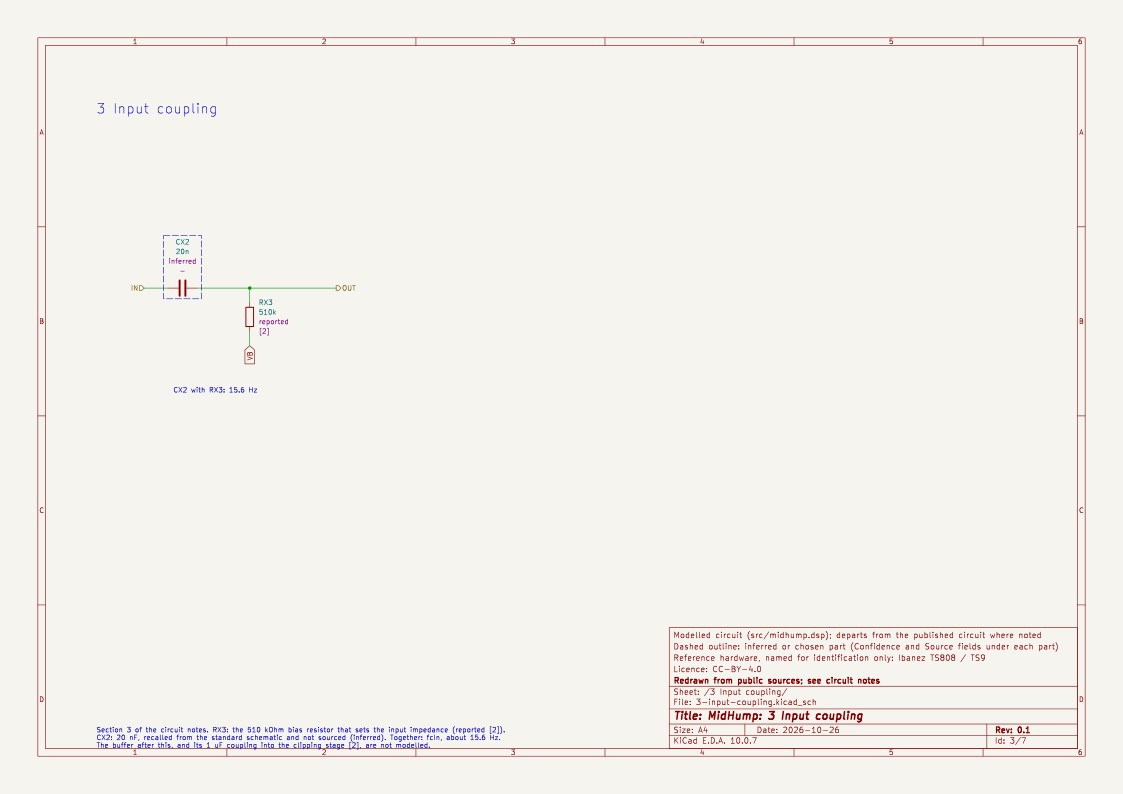
Inferred: a 20 nF coupling capacitor into a 510 kΩ bias resistor gives a high-pass at
f = 1 / (2π · 510 kΩ · 20 nF) ≈ 15.6 Hz
The 510 kΩ bias resistor is reported [2], which says it sets almost all of the input impedance. The capacitor value is recalled from the standard schematic, not sourced. [2] also says the buffer feeds the clipping stage through a 1 µF capacitor, "large enough" to pass the bass, so that coupling is not modelled. The effect on bass is small (−0.4 dB at 41 Hz). It is the fcIn constant in src/midhump.dsp.
4. Clipping stage
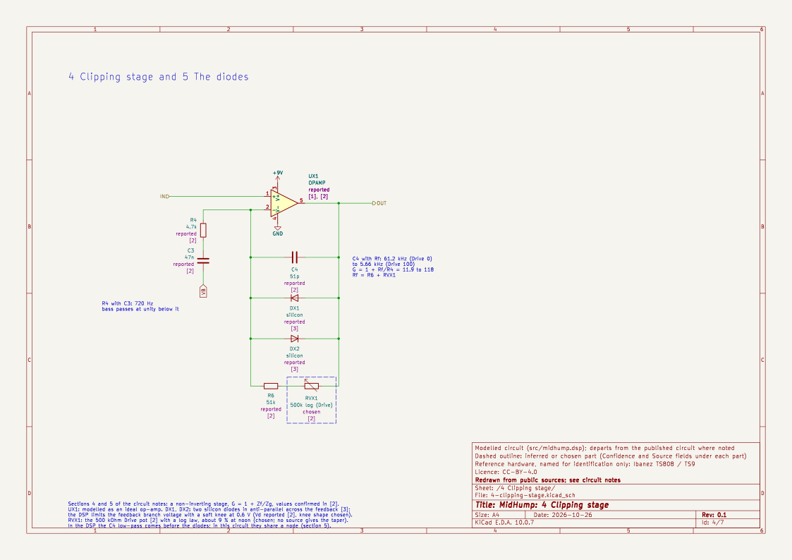
Reported [1], [2], values confirmed in [2]: a non-inverting op-amp stage. The gain is
G = 1 + Zf / Zg
- The grounded leg Zg is R4 = 4.7 kΩ in series with C3 = 47 nF.
- The feedback impedance Zf is R6 = 51 kΩ plus the Drive pot (500 kΩ) in series, in parallel with C4 = 51 pF and two antiparallel silicon diodes.
Because Zg contains a capacitor, the gain depends on frequency:
G(s) = 1 + (Rf / R4) · HP(s) · LP(s)
- HP is a first-order high-pass at 1 / (2π · R4 · C3) ≈ 720 Hz (reported [2]).
- LP is a first-order low-pass at 1 / (2π · Rf · C4). It is 61 kHz at Drive 0 and about 5.7 kHz at Drive 100 (both reported [1]).
- The gain range is 1 + 51 kΩ / 4.7 kΩ ≈ 11.9 (21.5 dB) to 1 + 551 kΩ / 4.7 kΩ ≈ 118 (41.5 dB) (reported [1]). [2] gives the same expression but states the result as "107 (about 44 dB)". Neither figure matches its own arithmetic, so MidHump follows the component values, and the measured range is 20.9 dB to 40.4 dB at 2 kHz (measured).
Below 720 Hz the second term vanishes, so the stage passes bass at unity gain and amplifies mids. The output is always the input plus the clipped branch. The sum is the reason the pedal never goes fully square, and the reason for the hump.
Chosen: Drive pot law. No source gave the taper. MidHump uses a logarithmic (audio) law, Rd = 500 kΩ · (10^(2·Drive) − 1) / 99, about 9 % of the pot at noon. This is the same law as BassDrive's gain pot. It puts the noon gain at 1 + (51 + 45) kΩ / 4.7 kΩ ≈ 21 (26.7 dB).
5. The diodes
Reported [3]: two silicon diodes in antiparallel in the feedback loop, which limit the voltage across Zf. Yeh models them with the Shockley equation and solves the circuit numerically.
Chosen model: the diodes limit the feedback branch voltage (Zf's drive, Vout − Vin). The model is a memoryless pk.softSat(Vd) with Vd = 0.6 V, run at 4x oversampling. The 720 Hz high-pass and the C4 low-pass sit outside the oversampler. This follows the simplification in [3] and [4], where the capacitor and diodes share one node. [3] compares such a static (memoryless) approximation with numerical solutions of the circuit's ODE.
- 0.6 V is reported [2]: silicon signal diodes "with a turn on voltage of about 0.5 to 0.6v", going from open circuit to a few ohms between about 0.4 V and 0.7 V. The knee is softer than a hard clip and harder than a real exponential diode. The knee shape is chosen.
- The clipper is symmetric, so the distortion is odd-order (reported [1]).
Known approximation: in the circuit, C4 and the diodes act together on the feedback node, so the low-pass acts on the clipped signal as well. In this model the low-pass comes before the clipper. At high Drive that leaves more high-frequency energy in the clipped waveform than the pedal has, and the 723 Hz passive filter that follows hides most of it.
6. Passive low-pass
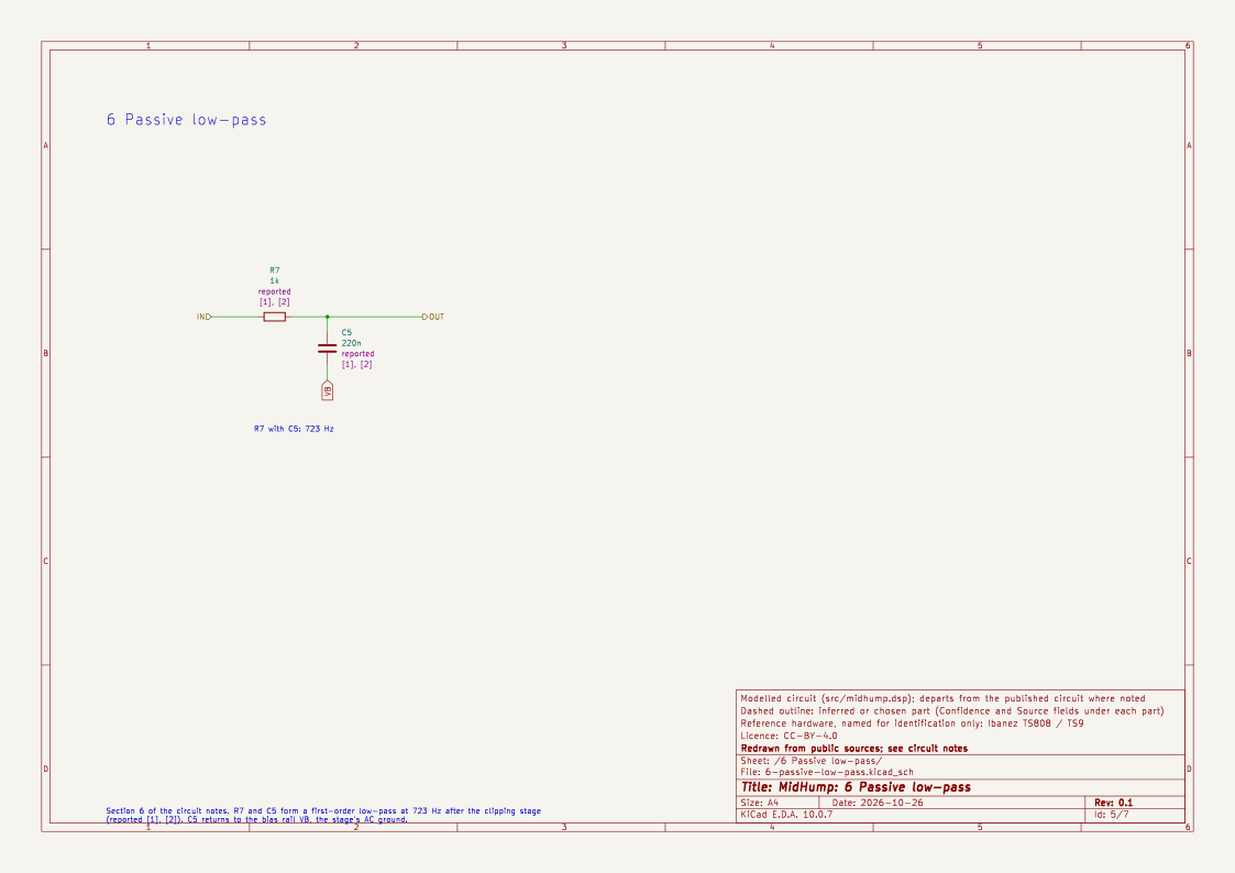
Reported [1], [2]: R7 = 1 kΩ and C5 = 220 nF form a first-order low-pass at 723 Hz after the clipping stage. It removes the harsh upper harmonics. MidHump uses fi.lowpass(1, 723).
7. Tone stage
Reported [1], [5]:
- The active tone stage boosts treble to compensate for the passive low-pass above. At full treble the response is roughly levelled; at full bass the 20 dB/decade slope of the passive filter remains.
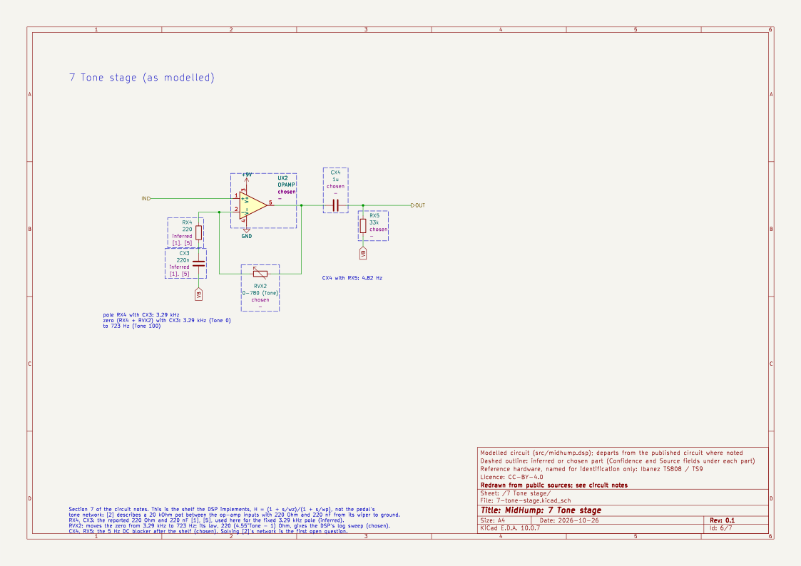
- A 220 Ω resistor in series with a 220 nF capacitor is part of the network. Above its corner of 1 / (2π · 220 Ω · 220 nF) ≈ 3.29 kHz the pair behaves like the 220 Ω alone.
Reported [2], read after the shelf below was written: the tone control is a 20 kΩ pot strung between the (−) and (+) inputs of the second op-amp, which is a unity-gain non-inverting stage. The wiper goes to ground through 220 Ω in series with 220 nF. That series network looks like the 220 Ω alone above about 3.2 kHz, and is large against the 20 kΩ pot below about 36 Hz. With the pot fully towards (+), the network shunts the signal above 3.2 kHz to ground, adding a further −6 dB/octave there. With it fully towards (−), it shunts the feedback above 3.2 kHz, giving +6 dB/octave of treble boost above 3.2 kHz, which "levels off" the 723 Hz roll-off rather than boosting above it.
Mismatch with the current model: in [2] the moving corner sits at about 3.2 kHz at both ends: a cut (a pole) at full bass, and a boost (a zero) at full treble. The shelf below keeps a fixed pole at 3.29 kHz and moves a zero from 3.29 kHz down to 723 Hz. At Tone 0 it is flat where [2] has an extra roll-off. At Tone 100 it is flat from 723 Hz to 3.29 kHz and falls above, where [2] falls from 723 Hz to 3.2 kHz and then levels off. The DSP has not been changed yet: solving the pot network from [2] is the first open question.
As implemented: the first draft could not read a netlist for the tone stage, and the accounts it saw disagreed on whether the 220 Ω network makes a boost or a cut. So MidHump does not solve the pot network. It uses a first-order shelf whose corners are the two reported frequencies:
H(s) = (1 + s / ωz) / (1 + s / ωp), with fp = 3.29 kHz and fz = fp · (723 Hz / fp)^Tone
- At Tone 0, fz = fp and H = 1. Only the 723 Hz low-pass remains.
- At Tone 100, fz = 723 Hz. The zero cancels the passive pole, so the stage after the clipper is flat up to 3.29 kHz and then falls at 20 dB/decade.
- In between, the zero moves logarithmically. The treble boost over the whole range is 20 · log10(3.29 kHz / 723 Hz) ≈ 13.2 dB.
This is chosen (the law) and inferred (the corners). It is not a circuit solution and, as above, it does not match [2]. Replacing it with the real network is the first item under open questions.
The schematic draws the shelf as implemented, not [2]'s network: a non-inverting stage whose ground leg is the reported 220 Ω and 220 nF (the fixed 3.29 kHz pole) and whose feedback is a 0 to 780 Ω Tone control that moves the zero from 3.29 kHz to 723 Hz, followed by the 5 Hz DC blocker.
8. Level and calibration
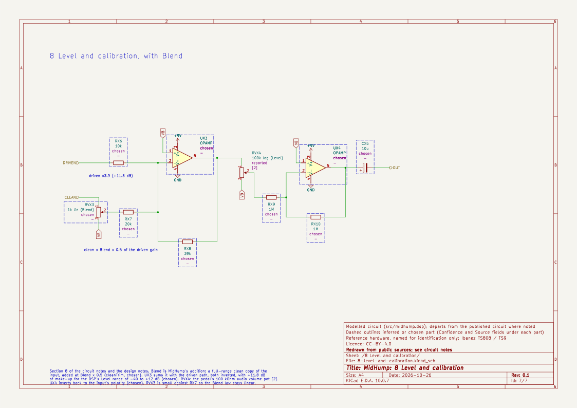
Chosen: Level is a plain gain in dB (−40 dB to +12 dB, default 0 dB), where the pedal has a passive volume pot and an output buffer. 1.0 digital full scale is treated as 1 V peak at the circuit input. At −12 dBFS the signal is 0.25 V peak. [2] puts a typical picked note at 30 mV to 100 mV, so the −12 dBFS test level is a hot pickup, and −30 dBFS to −20 dBFS is closer to an average one. The pedal's volume control is a 100 kΩ audio pot [2].
The schematic's last sheet adds Blend (see the design notes): an inverting summer takes the driven path at ×3.9 (+11.8 dB of make-up for the +12 dB Level range) and the clean path at Blend × 1.95, half the driven gain (cleanTrim). The pedal's 100 kΩ audio volume pot [2] and an inverting buffer that restores the polarity follow. All but the pot are chosen.
9. Summary of constants
| Constant | Value | Confidence |
|---|---|---|
fcIn |
15.6 Hz | Inferred |
R4, C3 (720 Hz) |
4.7 kΩ, 47 nF | Reported |
R6, Rpot |
51 kΩ, 500 kΩ | Reported |
| Drive law | log, ≈ 9 % at noon | Chosen |
C4 |
51 pF | Reported |
Vd |
0.6 V | Reported [2] (knee shape chosen) |
| Passive low-pass | 723 Hz | Reported |
| Shelf corners | 723 Hz, 3.29 kHz | Inferred (corners reported [2]; their use differs from [2]) |
| Shelf law | log-interpolated zero | Chosen |
| Level range | −40 to +12 dB | Chosen |
Sources
- ElectroSmash, Tube Screamer Circuit Analysis: https://www.electrosmash.com/tube-screamer-analysis. Read through search summaries and mirrors only, not the original page (the host did not resolve in October 2026).
- R. G. Keen, The Technology of the Tube Screamer, Geofex: http://www.geofex.com/Article_Folders/TStech/tsxtech.htm. Read directly in October 2026.
- D. T. Yeh, J. Abel and J. O. Smith, Simulation of the diode limiter in guitar distortion circuits by numerical solution of ordinary differential equations, DAFx-07: https://www.dafx.de/paper-archive/2007/Papers/p197.pdf. Read directly in October 2026. It covers the diode clipper with an RC low-pass, not this pedal's component values.
- D. T. Yeh, Digital Implementation of Musical Distortion Circuits by Analysis and Simulation, PhD thesis, CCRMA, Stanford, 2009: https://ccrma.stanford.edu/~dtyeh/papers/DavidYehThesissinglesided.pdf. Not read in this session.
- ElectroSmash, JRC4558 analysis, for the op-amp choice: https://www.electrosmash.com/jrc4558-analysis/pedals/distortion/jrc4558-analysis.html. Not read in this session. The op-amp is modelled as ideal.
- m0xpd, Shack Nasties: Analysis of the Tube Screamer (tone stage as a first-order shelf with a 220 nF complication): https://m0xpd.blogspot.com/2012/11/analysis-of-tube-screamer.html. Read through a search summary only.
Open questions
- The tone stage: solve the 20 kΩ pot, 220 Ω and 220 nF network around a unity-gain op-amp as [2] describes it (section 7), check it against [1], and replace the shelf. This changes the sound at every Tone setting, so it needs a version bump and new preset levels.
- The input coupling capacitor, and the 10 kΩ and 1 µF values in the buffer.
- Whether to move the C4 low-pass after the clipper, as in the circuit, at the cost of a filter inside the oversampled path.
- The diode knee. Yeh's numerical solution would settle the shape of the soft clipper.
- How the Drive pot is tapered in the pedals people play. A linear pot would change every noon figure above.
- The citation for the 220 Ω and 220 nF pair in section 7, "[1], [5]". Source [5] is the op-amp article; the tone-stage analysis is [6]. The schematic follows the notes as written until this is checked.
- Whether C5 returns to ground or to the bias rail. The schematic takes the bias rail; at audio frequencies they are the same.