Circuit notes: modelling the ODB-3
These notes summarise what public sources say about the Boss ODB-3 bass overdrive. They also record how BassDrive turns that into DSP. "Boss" and "ODB-3" appear here only to identify the reference pedal. The plugin carries none of that branding.
No proprietary plugin or firmware was inspected. Everything below comes from the sources listed at the end, plus standard circuit analysis.
Each section with component values has a sheet of the KiCad schematic, redrawn from these notes. No public schematic of the pedal was found, so the schematic is the circuit BassDrive implements, not a trace of the pedal, and most of its parts are inferred or chosen. Dashed outlines mark those parts, and designators with an X (RX1, UX2 …) mark parts no source names.
Confidence levels used throughout:
- Documented: stated by the manufacturer.
- Reported: stated by one or more third parties (a forum post, review or measurement). It hasn't been checked against a schematic.
- Inferred: my own reasoning from the reported facts.
- Chosen: a free modelling choice where no source gives a value.
1. Controls and interface (documented)
The manufacturer's page [1] lists:
| Control | Function |
|---|---|
| GAIN | Amount of drive |
| BALANCE | Mix of dry and overdriven sound |
| EQ LOW | Low band |
| EQ HIGH | High band |
| LEVEL | Output volume |
Specifications: nominal input −20 dBu, input impedance 1 MΩ, output impedance 1 kΩ, buffered bypass, 9 V supply [1].
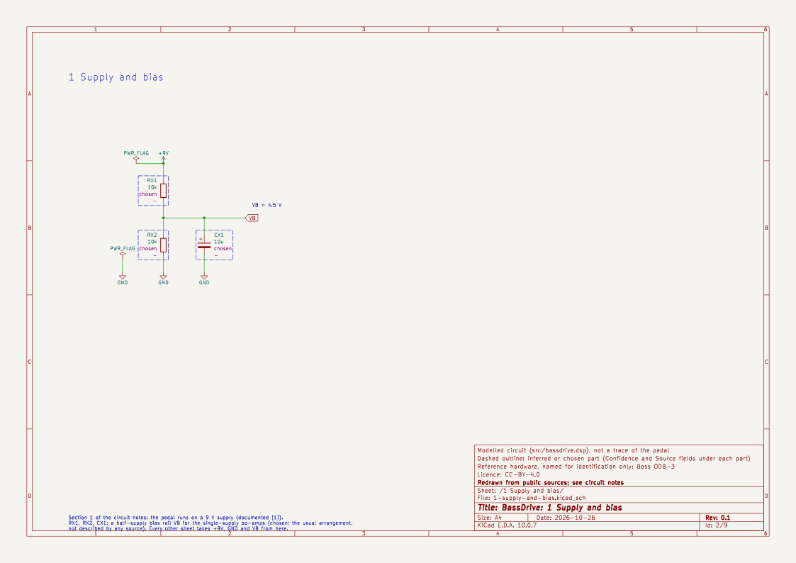
The schematic's first sheet holds the 9 V supply and a half-supply bias rail, VB, for the single-supply stages. Neither is described by a source, so both are chosen.
Retailer copy says the pedal can also be used as a plain two-band EQ [3]. Inferred: the EQ therefore sits after the clean/driven blend and acts on both signals. BassDrive follows this.
2. Overall topology
- Reported: the core of the overdrive is "a two-stage cascaded discrete circuit", with LED clipping in the second stage [4].
- Reported: an ODB-3-derived DIY board (GCI "N.E.W. Bass Overdrive") swaps the pedal's RC4558 op-amps for TL092s and its 2SK184 JFETs for 2N5457s [5]. So the pedal has op-amps (probably buffers, mixing and the EQ) and JFETs (the usual Boss electronic switching [4]).
- Reported: the clipping elements are two LEDs, D2 and D3, in anti-parallel [2]. A poster in the same thread puts their forward voltage at about 1.5 V [2].
Inferred block diagram:
in → buffer ─┬─────────────── clean ──────────────┐
             │                                     ├─ BALANCE ─ EQ (low/high) ─ LEVEL ─ out
             └─ stage 1 (gain, pre-emphasis) ─ stage 2 (LED clip) ─ post filter ┘
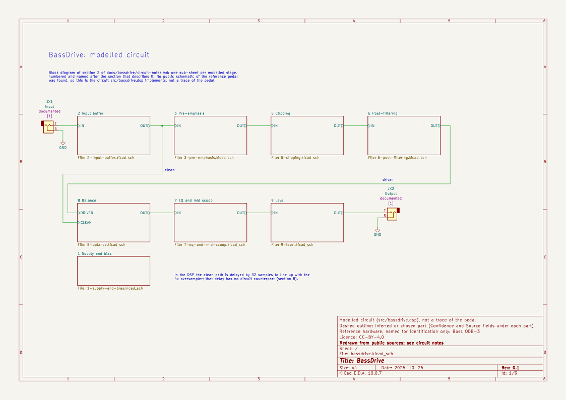
The schematic's root sheet is this block diagram, with one sub-sheet per stage:
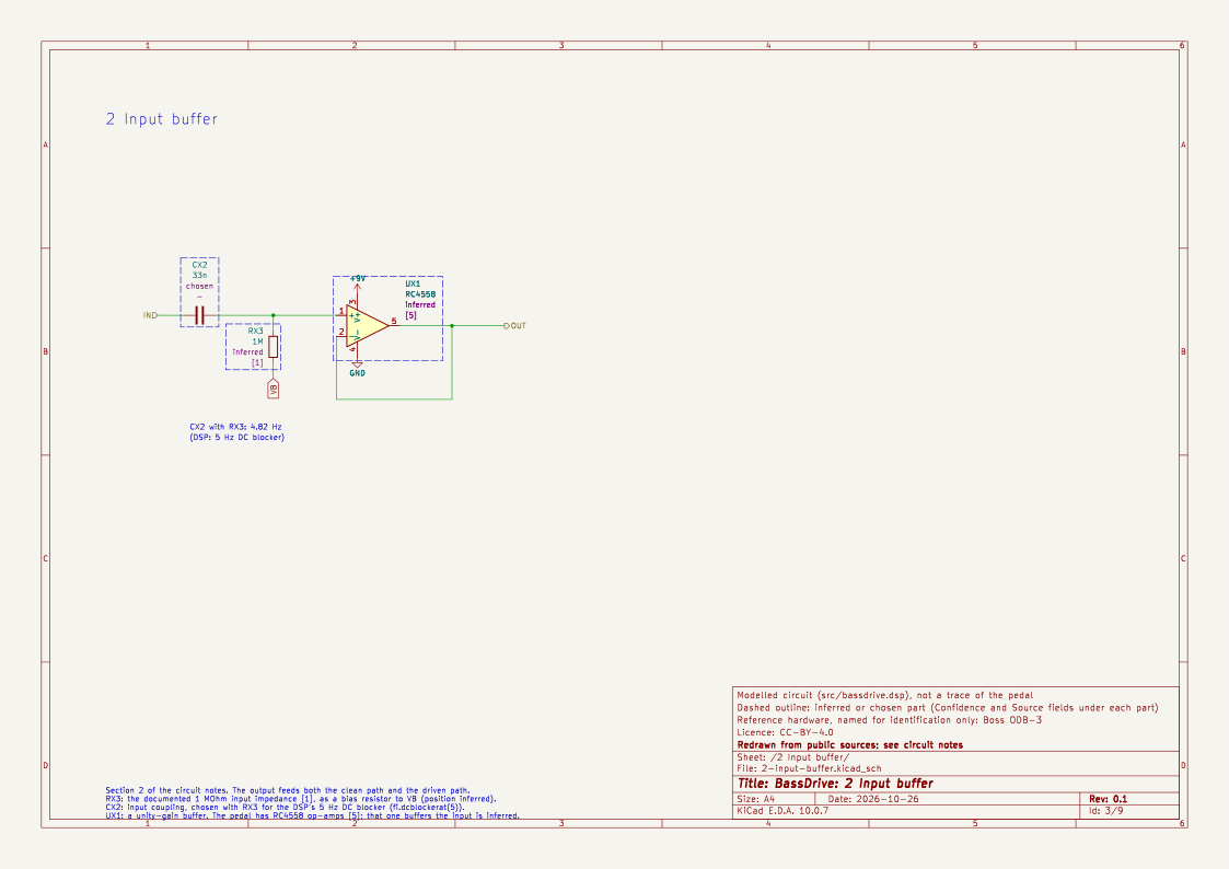
The input buffer is drawn with the documented 1 MΩ input impedance [1] as its bias resistor, and a coupling capacitor chosen for the DSP's 5 Hz DC blocker. That one of the pedal's op-amps [5] buffers the input is inferred.
3. Pre-emphasis (stage 1): R31 and C10
A widely circulated mod [2] changes:
- R31: 3.3 kΩ → 1 kΩ
- C10: 33 nF → 1–2.2 µF
- C8: 300 pF → 1 nF
The author says the stock pedal sounds "thin", "a treble layer over the clean tone", and that the mod makes it fuller. A separate post reports that removing C10 together with the LEDs turns the pedal's mid scoop into a mid hump [4].
Inferred: R31 and C10 form the series RC shunt leg of a non-inverting gain stage, the same arrangement as the familiar Tube Screamer's 4.7 kΩ and 47 nF. With the stock values the corner is
f = 1 / (2π · 3.3 kΩ · 33 nF) ≈ 1.46 kHz
The stage gain is then 1 + (Rf / R31) · HP₁(f). Below about 1.5 kHz the signal passes at roughly unity, and above it the gain rises towards 1 + Rf/R31. This explains both reports: the stock pedal adds distortion mainly to the upper register (thin, "treble layer"), and the mod drops the corner to about 72–160 Hz so the lows get driven too.
Uncertain: I haven't confirmed the position of R31 and C10 against a schematic. The interpretation fits every report, and it is the standard topology.
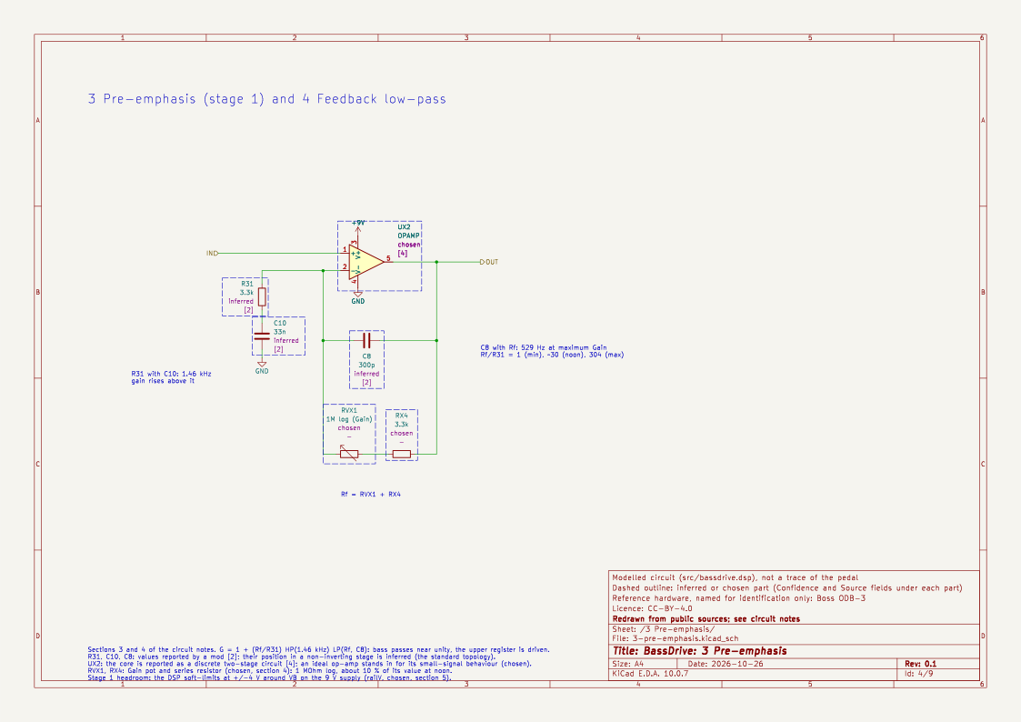
The sheet below draws this stage and the feedback network of section 4 as BassDrive models them.
4. Feedback low-pass: C8 and the Gain pot
Inferred: C8 (300 pF) sits across the feedback resistance (the Gain pot plus any series resistor). This limits HF gain with a corner of 1 / (2π · Rf · C8), which falls as Gain rises.
Chosen: no source gives the Gain pot's value. I model a 1 MΩ log-taper pot, a common value for this kind of stage, with 3.3 kΩ in series. A log pot sits at about 10 % of its resistance at mid-rotation. The ratio Rf/R31 therefore runs from 1 at minimum Gain, through about 30 at noon, to about 304 at maximum, and the C8 corner falls to about 530 Hz at maximum. The resulting band-pass emphasis around 0.5–3 kHz matches the reviewer's remark that at maximum Gain the clipping is "concentrated in higher registers" [6].
I tried an exponential map first (−6 dB to +40 dB). It hardly changed the distortion of bass notes below noon. With a first-order 1.46 kHz pre-emphasis, the drive on a 110 Hz fundamental is only 1 + k·0.075, so k has to reach several tens before low notes clip. The log-pot law fixed this.
5. Clipping (stage 2)
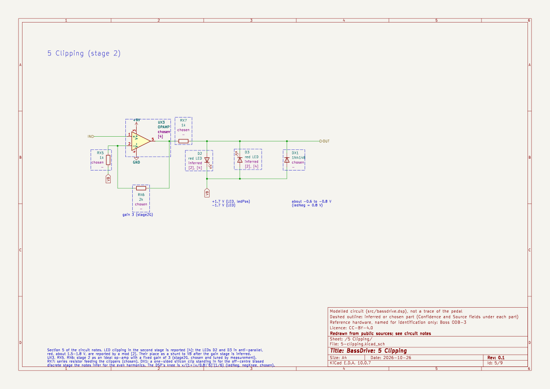
- Reported: red LEDs in anti-parallel, described as "smooth but aggressive" [2]. The forward voltage is about 1.5–1.8 V [2].
- Reported (measurement) [6]:
- Gain at minimum: light overtones, mostly odd-order, with fairly symmetrical clipping.
- Gain at noon: the overtones become mainly even-order, and the waveform turns sawtooth-like.
- Gain at maximum: heavier, more sawtooth-like.
Inferred: matched LEDs alone would give odd-order harmonics. The even-order content, and the way it grows with Gain, points to asymmetry somewhere else, most plausibly a discrete transistor stage biased off-centre on the 9 V supply. Clipping one side of the waveform earlier than the other produces exactly that sawtooth-like shape.
Chosen model: a memoryless chain run at 4x oversampling:
- A mild symmetric soft saturation at ±4 V for stage 1's headroom on a 9 V supply.
- A fixed stage-2 gain of 3x (assumed, and tuned so the measured harmonic trends below match the reference).
- A hybrid clipper (
pk.asymSoftHard): - Positive side: soft tanh clipping at +1.7 V (red LED).
- Negative side: a harder knee, x / (1 + |x/0.8|⁶)^(1/6), limiting at −0.8 V. This stands in for the biased transistor stage running out of headroom on one side. Its level and hardness are choices.
Why this shape: I tried three kinds of asymmetry, and only this one reproduced the reported trend (light and odd at minimum Gain, even-leaning by noon).
- Plain tanh with unequal knees gave odd-dominant harmonics at every Gain.
- A DC bias into the clipper made the even harmonics dominate even at minimum Gain, which contradicts [6].
- The hard negative knee does nothing at low level, then clips one side first as the drive rises.
Measured on single sines at −12 dBFS (driven path only):
| Gain | 41 Hz THD | 41 Hz H2 / H3 | 110 Hz THD | 110 Hz H2 / H3 |
|---|---|---|---|---|
| 0 % | 2.2 % | −48 / −34 dBc | 1.4 % | −48 / −38 dBc |
| 50 % | 5.9 % | −30 / −26 dBc | 12.5 % | −20 / −22 dBc (even leads) |
| 100 % | 30.5 % | −21 / −12 dBc | 27.5 % | −31 / −15 dBc |
At maximum Gain, both sides clip hard and the odd harmonics take over again. The reference describes that setting as "sawtooth-like", which suggests more even content than I get. This is the main harmonic mismatch I know of.
The schematic draws stage 2 as an op-amp with the fixed gain of 3, then D2 and D3 as a shunt to VB, then a silicon diode, DX1, that clips the negative side first. DX1 stands in for the biased discrete stage; its knee, about −0.6 V where the DSP uses −0.8 V, is only indicative.
6. Post-filtering
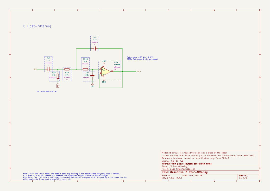
Chosen: a 2nd-order low-pass at 5 kHz on the driven path, then a 5 Hz DC blocker to remove the offset created by the asymmetric clipper. The real post-filter is not documented. 5 kHz keeps the fizz above the treble band in check while leaving the High control (below) something to act on. Below 11.1 kHz sample rate the corner is held at 0.45 × the sample rate, because a corner at or above Nyquist makes the digital filter unstable.
7. The EQ and the fixed mid scoop
Reported (measurement) [6]:
| Setting | Low | High | Mid scoop |
|---|---|---|---|
| Min | ~−12 dB around 110 Hz (narrow) | rolls off above ~2 kHz at ~3 dB/oct | ~6 dB |
| Noon | about flat | ~+10 dB broad boost around 3 kHz | ~6 dB, centred ~350 Hz |
| Max | ~+12 dB around 110 Hz | ~+16 dB broad boost around 7 kHz | — |
A reviewer also notes that the High control does most of the useful work [3].
Chosen:
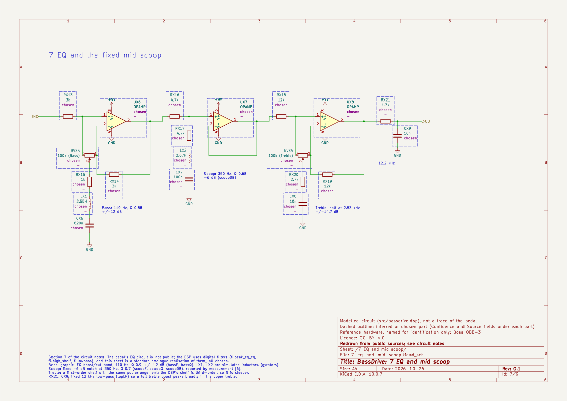
- Bass: a peaking filter at 110 Hz, Q 0.9, ±12 dB.
- Treble: a high shelf at 2.5 kHz, ±15 dB, followed by a fixed 1st-order low-pass at 12 kHz so that a full boost peaks broadly in the upper treble rather than rising without limit. Below 26.7 kHz sample rate it is likewise held at 0.45 × the sample rate.
- Mid scoop: a fixed peaking cut of −6 dB at 350 Hz, Q 0.7, always in circuit. The measurement shows it at every EQ setting, and the C10 report [4] ties it to the circuit rather than the EQ. In my model, some of the scoop also comes naturally from the phase difference between the clean and pre-emphasised driven paths when they are blended. The fixed cut is a pragmatic stand-in. It is a constant in the source,
scoopDB, and can be tuned.
Deliberate difference: on the real pedal, noon on High is already about +10 dB. For a plugin, a calibrated "0 dB is flat" scale is more useful. If you want the original's voicing, set Treble to about +10 dB.
The EQ's circuit is not public and the DSP uses digital filters, so the schematic draws a standard analogue stand-in, every part chosen: graphic-EQ boost/cut bands for Bass and Treble (flat with the pot centred, full boost or cut at the ends), a series RLC shunt for the scoop, and an RC low-pass at 12 kHz. Its script checks that the values give the DSP's centre frequencies, Q factors and ranges. The inductors would be gyrators in practice. The treble shelf here is first-order where the DSP's is third-order.
8. Balance
Documented: a dry/overdriven blend [1].
Reported: on the related Boss Bass OD, the clean side of the blend is quieter than the drive side [7]. That pedal is not the ODB-3, so treat this as a hint only.
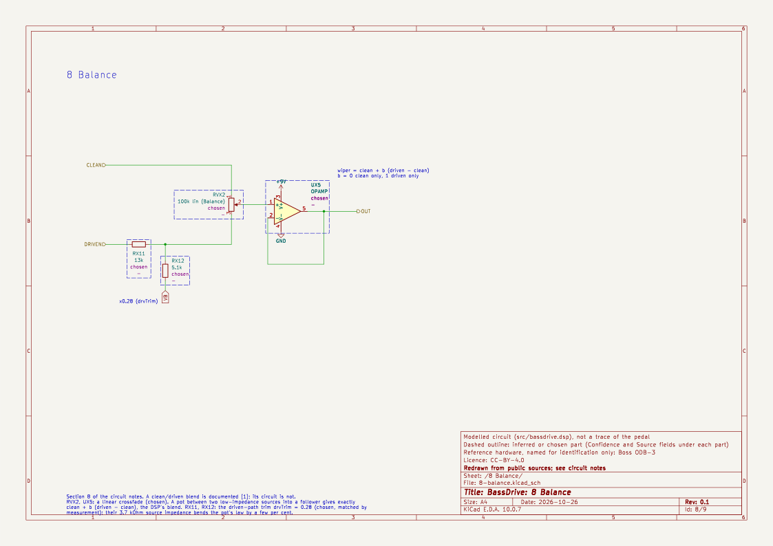
Chosen: a linear crossfade, 0 % fully clean to 100 % fully driven. The driven path is trimmed (drvTrim = 0.28) so that a bass-like test tone (a 55 Hz band-limited sawtooth) comes out within about 1.5 dB of the clean path at Gain 0–50 %. At Gain 100 % the driven path is about 2 dB louder, as on most overdrives. The clean path is unfiltered apart from the DC blocker, so it keeps the full low end.
Latency compensation: the 4x oversampler delays the driven path by a whole number of samples (32). The clean path is delayed by the same amount so the blend doesn't comb-filter at low frequencies.
Measured side effect: at a 50/50 blend the two paths still cancel at one frequency in the upper treble. There, the driven path's phase lag (C8 plus the post-filter) reaches 180° while its level equals the clean path. The notch sits around 5.8 kHz at full Gain and 7.7 kHz at noon. Moving the post-filter only shifts it. A real summing blend with this topology would behave the same way, so I've kept it, but it is worth listening for.
A pot between two low-impedance sources, read by a follower, gives exactly this crossfade, so that is what the schematic draws, with a divider for drvTrim:
9. Levels and calibration
Chosen: 1.0 digital full scale is treated as 1 V peak at the circuit input. A DI'd bass peaking around −12 dBFS then sits near the pedal's nominal −20 dBu (about 0.11 V peak) plus some headroom. This is what makes the LED threshold land in a sensible place.
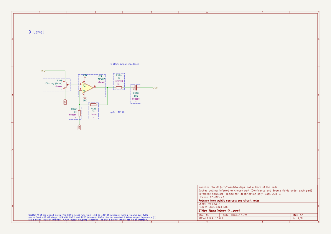
Chosen: Level runs from −40 dB to +12 dB. The schematic draws it as a volume pot followed by a fixed +12 dB stage, with the documented 1 kΩ output impedance [1] as a series resistor:
Sources
- Manufacturer's product and specification page: https://www.boss.info/us/products/odb-3/
- "Boss ODB-3 Bass Overdrive mod", BassBuzz forum (component values R31/C10/C8, LED clippers, diode alternatives): https://forum.bassbuzz.com/t/boss-odb-3-bass-overdrive-mod/13162
- Thomann product page (EQ usable on its own, Balance description): https://www.thomann.de/ie/boss_odb-3_bass_overdrive.htm. A review noting where the EQ is most useful: https://www.awkwardsound.com/boss-odb-3-bass-overdrive-review/
- freestompboxes.org, "Boss ODB-3 bass overdrive" (two-stage discrete core, LED clipping in stage 2, C10 and mid scoop, JFET switching). The site refused automated fetching, so I worked from search-engine summaries of the thread rather than reading it in full: https://www.freestompboxes.org/viewtopic.php?t=30932
- PedalPCB forum, "N.E.W. Bass Overdrive: ODB-3 on Steroids" (RC4558 and 2SK184 in the original): https://forum.pedalpcb.com/goto/post?id=170021
- Guitar Pedals Visualized, "Boss ODB-3" (EQ frequency-response and harmonic measurements): https://guitarpedalsvisualized.wordpress.com/2024/09/16/boss-odb-3/
- DIYStompboxes forum, "Boss Bass OD; any mods??" (blend level remark, related pedal). Also refused automated fetching, so this is a search summary: https://www.diystompboxes.com/smfforum/index.php?msg=451976
Open questions to settle by ear or with a schematic
- The Gain pot value, and so the true range of Rf/R31 and the C8 corner.
- Stage 2's fixed gain, and whether it is really the stage with the asymmetry.
- The exact post-clip filtering.
- Whether the mid scoop comes from the blend's phase interaction, a dedicated network, or both.
- Where the LEDs sit. The schematic draws them as a shunt after stage 2 (inferred); in the feedback loop of a gain stage they would clip the stage's gain rather than its output, with a softer knee. The memoryless DSP model can't tell the two apart, but a circuit-level model would.