Circuit notes: the op-amp hard-clipping distortion
These notes record what public sources say about the classic op-amp distortion pedal that BassGrit borrows from (the Pro Co RAT), and how BassGrit turns that into DSP. The manufacturer and product names appear here only to identify the reference hardware. The plugin carries none of that branding.
No proprietary plugin or firmware was inspected. Everything below comes from the sources at the end, plus standard circuit analysis.
Status of these notes
The first draft was written in a session that could not open ElectroSmash [1]: the connection failed. Its values came from search-engine summaries and from recall of the standard schematic. In October 2026 the PedalPCB build document for a RAT-style clone [6] was read directly. Its parts list confirms most component values, and they are now marked reported [6]. [1] was still unreachable (the host does not resolve), and its schematic image was read for the wiring. The gain-bandwidth product, the diode clip level and the knee are still inferred or chosen.
Confidence levels used throughout:
- Documented: stated by the manufacturer, a datasheet or a cited paper.
- Reported: stated by one or more third parties (an analysis, a forum post or a measurement). Where only a summary was seen, the text says so.
- Inferred: my own reasoning from the reported facts, or recall that no source in hand confirms.
- Chosen: a free modelling choice where no source gives a value.
This is the borrowed part only. The departures (the band split, the filter range, the output trim) are in the design notes.
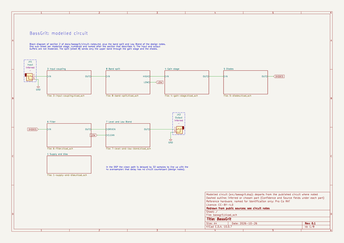
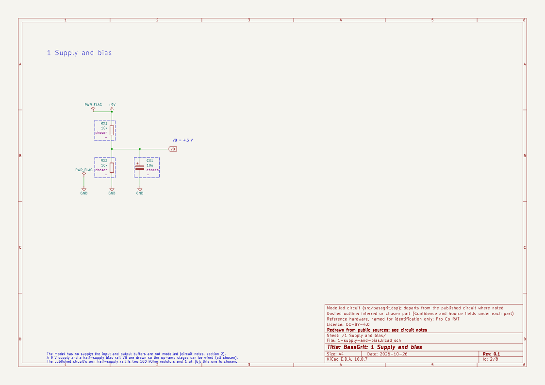
Each section with component values has a sheet of the KiCad schematic, redrawn from these notes and from the schematic in [6]. It is the circuit BassGrit implements: where the model departs from the published circuit (the input network, the Filter capacitor, the band split, Low Blend and Level), the sheet draws the model and says so. Dashed outlines mark inferred and chosen parts, and designators with an X (RX3, UX1 …) mark parts the notes do not name.
1. Controls and interface
The pedal has three controls: Distortion (the gain), Filter (a low-pass that darkens as it is turned up) and Volume [1]. BassGrit keeps the first two and adds Low Blend and Crossover (see the design notes).
2. Block diagram
in → input coupling → op-amp gain stage → series resistor + diode pair to ground → Filter → output buffer
The input and output buffers are not modelled (chosen): they match impedances, which a digital model has no use for.
The root sheet is this block diagram plus the band split of the design notes, with one sub-sheet per stage. Sheet 1 holds a 9 V supply and a bias rail, both chosen, so the op-amp stages can be wired.
3. Input and coupling networks
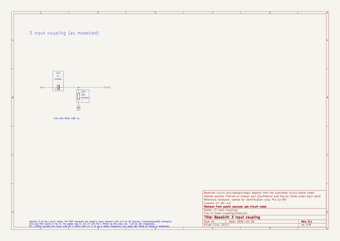
Read from the schematic in [6] (reported), with the corners derived:
- Input: C1 22 nF in series, with R1 1 MΩ to ground on the jack side and R2 1 MΩ to the half-supply bias rail VREF on the op-amp side. R2 is an AC ground, so the capacitor sees R2 alone, and the high-pass is f = 1 / (2π · 1 MΩ · 22 nF) ≈ 7.2 Hz. A 1 kΩ resistor (R4) and 1 nF (C4) to ground follow, a radio-frequency filter at about 159 kHz that is not modelled (chosen: it is outside the audio band).
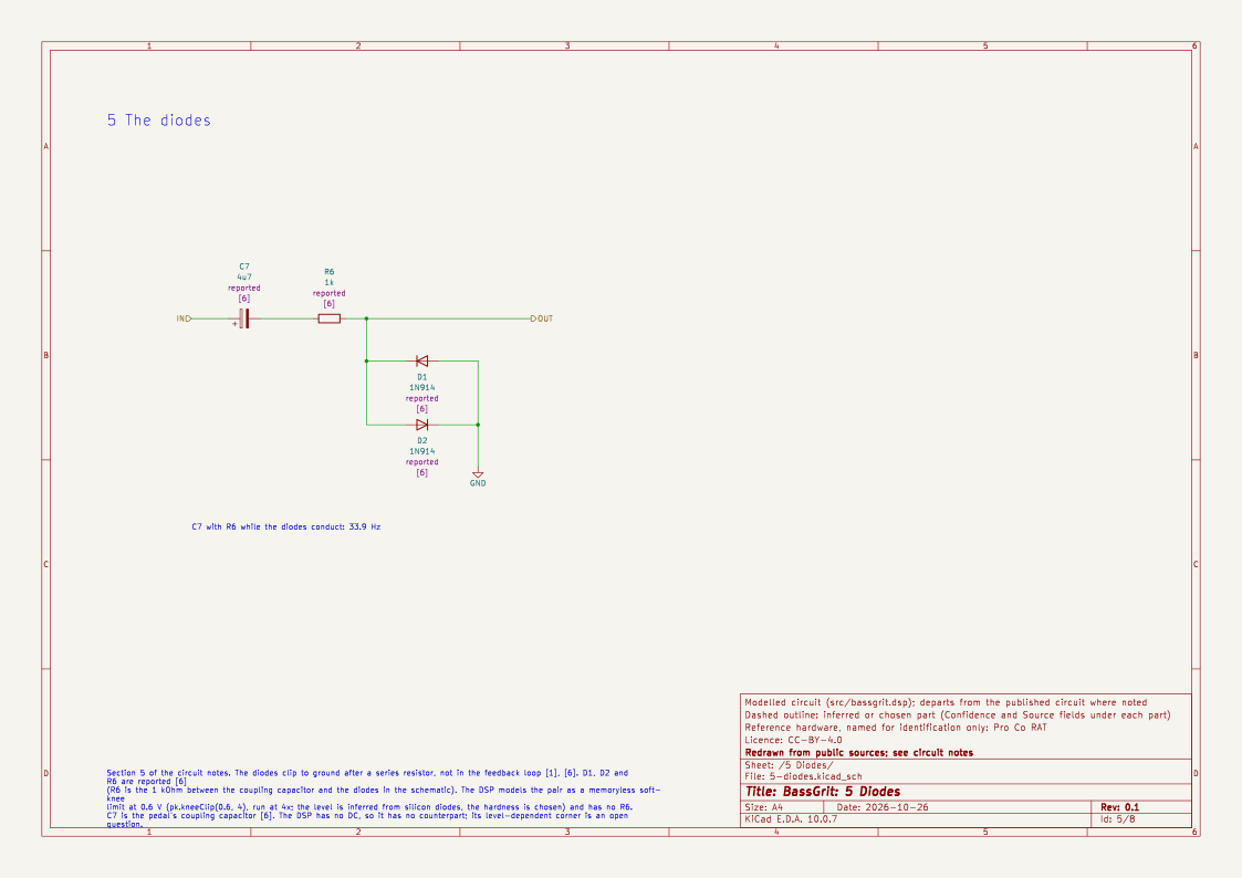
- Between the gain stage and the diodes: C7 4.7 µF and R6 1 kΩ. While the diodes conduct (heavy clipping) they form a high-pass at 1 / (2π · 1 kΩ · 4.7 µF) ≈ 34 Hz, and below the diode knee the load is far larger and the corner is far lower. This level-dependent coupling is not modelled (chosen; see open questions).
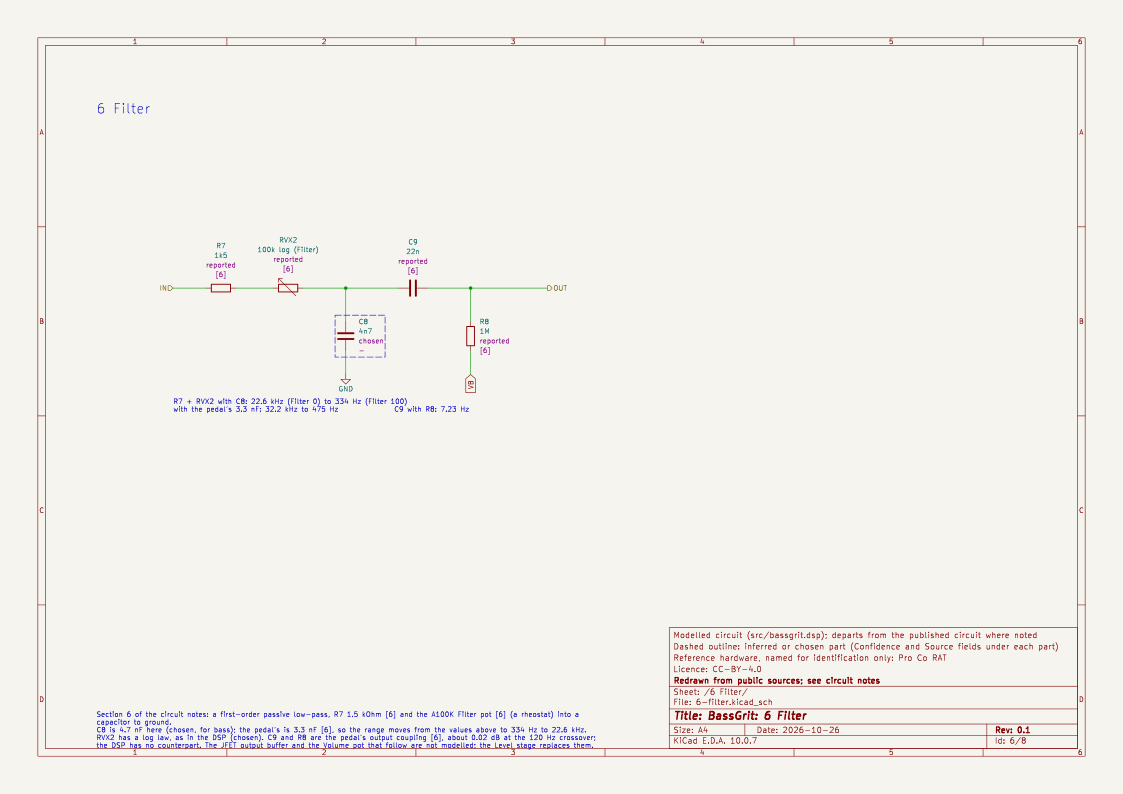
- Output: C9 22 nF into R8 1 MΩ before the JFET buffer, about 7.2 Hz, not modelled separately.
BassGrit replaces the input network with a 5 Hz DC blocker (fi.dcblockerat(5), chosen: a bass note at 31 Hz must pass at full level, and the difference from 7.2 Hz is 0.1 dB).
4. Gain stage
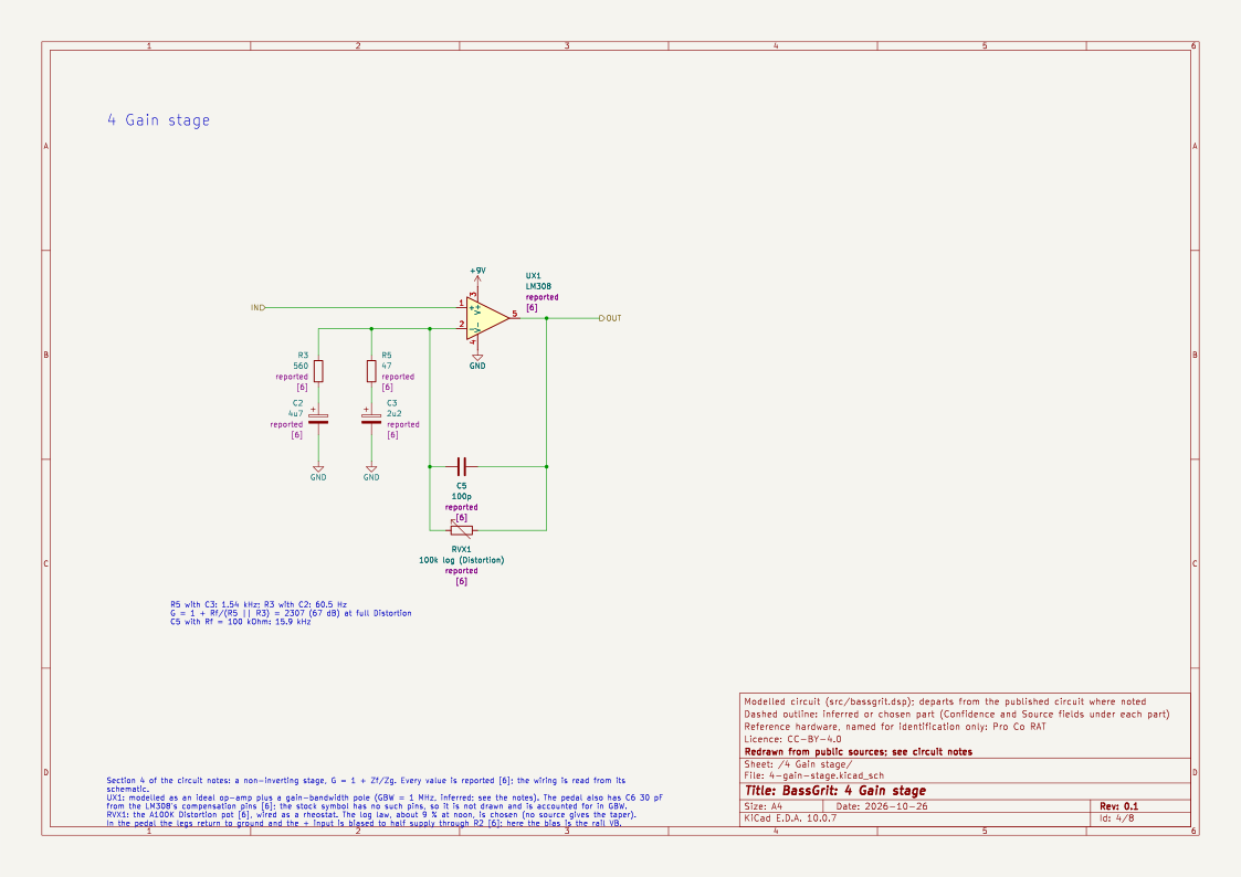
Reported [1], [3]: a non-inverting op-amp stage with gain
G = 1 + Zf / Zg
- The grounded side Zg is two RC legs in parallel: 47 Ω + 2.2 µF and 560 Ω + 4.7 µF (component values reported [1], [6]: R5 47 Ω, C3 2.2 µF, R3 560 Ω, C2 4.7 µF).
- The feedback side Zf is the Distortion pot (100 kΩ, audio taper, reported [6]) in parallel with 100 pF (reported [6], C5). [6] also lists a 30 pF ceramic (C6), which is the LM308's compensation capacitor and is not modelled separately: its effect is inside the GBW figure below.
Each leg is a first-order high-pass: its admittance is (1/R) · s/(s + ω). So
G(s) = 1 + Rf · [ HP_A(s) / 47 Ω + HP_B(s) / 560 Ω ] · LP(s)
- HP_A corner: 1 / (2π · 47 Ω · 2.2 µF) ≈ 1.54 kHz. HP_B corner: 1 / (2π · 560 Ω · 4.7 µF) ≈ 60.5 Hz. A forum estimate gives "roughly 60 Hz and 1500 Hz" [3] (reported).
- The gain at high frequency is 1 + 100 kΩ / (47 Ω ‖ 560 Ω) ≈ 2300 (67 dB) at full Distortion, falling to 1 at Distortion 0.
- At full Distortion the second leg alone gives 1 + 100 kΩ / 560 Ω ≈ 180 (45 dB) between 60 Hz and 1.5 kHz, and the first leg adds above that (derived from the reported values).
Gain-bandwidth limit. The pedal's op-amp is an LM308 (reported [1], [4]) with a small compensation capacitor, and its gain-bandwidth product sets the bandwidth at high gain: closed-loop bandwidth ≈ GBW / G. [4] says this drives the high-frequency roll-off at high Distortion. BassGrit uses GBW = 1 MHz (inferred: order of magnitude only; the datasheet was not read, and the real part varies from sample to sample [4]. [6] confirms the LM308 and the 30 pF compensation capacitor, but not the resulting GBW). That gives a closed-loop pole of about 430 Hz at full Distortion and about 4.8 kHz at noon.
The feedback capacitor adds a second low-pass at 1 / (2π · Rf · 100 pF): 16 kHz at full Distortion.
Distortion pot law. [6] lists an A100K (logarithmic, audio taper) pot (reported), but not the law's shape. BassGrit uses this logarithmic law (chosen), Rf = 100 kΩ · (10^(2·Distortion) − 1) / 99, about 9 % of the pot at noon. It is the same law as MidHump's Drive and BassDrive's Gain.
Model structure. As in MidHump, the op-amp output is the input plus a branch: out = in + (Zf / Zg) · in, the branch being the two scaled high-passes followed by the two low-passes. The op-amp's own rail limits (the output stage of a 9 V supply) are not modelled (chosen: see open questions).
5. The diodes
Reported [1]: two 1N914 (silicon switching) diodes, antiparallel, from the op-amp output to ground through a series resistor of 1 kΩ (R6, reported [6]: the schematic shows it between the coupling capacitor C7 and the diodes D1, D2). Unlike a diode-in-feedback overdrive, these clip to ground, after the gain stage, so the clipped signal is not added to the input. At high Distortion the output is close to a square wave of about ±0.6 V.
Chosen model: a memoryless pk.kneeClip(0.6, 4) run at 4x oversampling. The limit 0.6 V is inferred from the forward voltage of silicon diodes (about 0.5 V to 0.7 V). The knee hardness 4 is chosen: harder than a tanh and softer than a clamp. Changing it from 1.5 to 4 moves the worst alias by only 3 dB (the clipper input is far above threshold), so the choice matters for tone, not for aliasing.
The 1 kΩ series resistor and the diodes also load the Filter's source impedance; its 1.5 kΩ is far larger, and the interaction is not modelled (chosen).
6. Filter
Reported [1] (summary): a first-order passive low-pass: a 1.5 kΩ resistor (R7) in series with an A100K pot (a rheostat: wiper tied to one end), into 3.3 nF (C8) to ground (all reported [6]). The corner is
f = 1 / (2π · (1.5 kΩ + Rpot) · 3.3 nF)
which runs from 32.2 kHz (pot at 0) down to 475 Hz (pot at 100 kΩ) (derived). Turning the knob up darkens the sound. BassGrit keeps the structure and the law and changes the capacitor to 4.7 nF (see the design notes), giving 22.6 kHz to 334 Hz.
7. Level and calibration
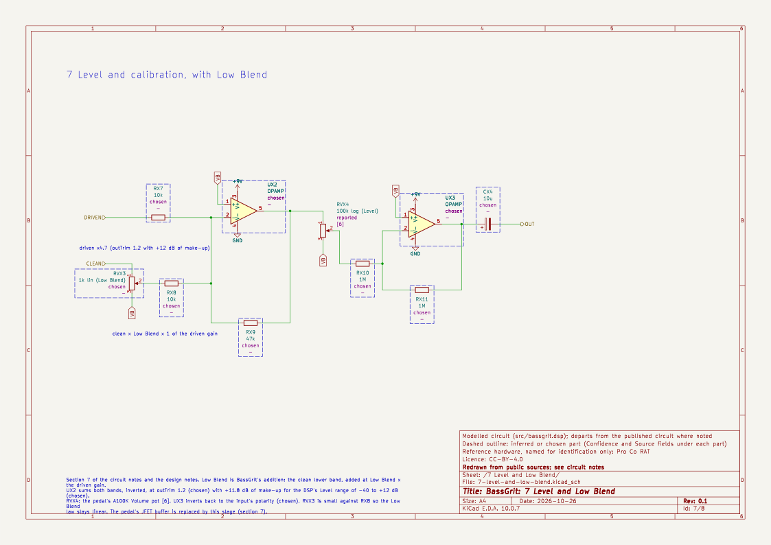
Chosen: 1.0 digital full scale is treated as 1 V peak at the circuit input. The 0.6 V clip then sits at −4.4 dBFS, and an outTrim of 1.2 restores some of the level (see the design notes). The pedal's volume stage is replaced by a plain gain in dB.
Sources
- ElectroSmash, ProCo RAT analysis. Not fetched in the session that wrote these notes; values from the parts list and summary in search results.
- PedalPCB, Muroidea (RAT) build thread. Input coupling, filter and the substitute op-amps.
- DIYStompboxes, Proco Rat Redesign. The two grounded legs and their approximate corners.
- PedalPCB, forum post on the LM308's gain-bandwidth product.
- Wikipedia, Pro Co RAT. History only.
- PedalPCB, Muroidea Distortion build document (revised 10/21/23). Parts list read directly: R3 560 Ω, R5 47 Ω, R7 1.5 kΩ, R4 and R6 1 kΩ, C1 22 nF, C2 4.7 µF, C3 2.2 µF, C5 100 pF, C6 30 pF, C8 3.3 nF, 1N914 diodes, LM308, A100K pots. The schematic image in the same document was also read: it fixes the wiring (section 3, 4, 5 and 6).
Open questions
- Check the LM308's GBW at 30 pF (datasheet) and the supply voltage (the schematic in [6] shows a 9 V pedal supply with a VREF half-supply divider). The component values and wiring are now reported [6]; ElectroSmash [1] is still unread.
- The 34 Hz high-pass of C7 with R6 while the diodes conduct is not modelled. Does it thin a clipped low note?
- Does the LM308's output swing (slew and rail limits) add clipping before the diodes at high Distortion? The model has none.
- Should the diodes be modelled with the Shockley equation rather than a static knee? the MidHump circuit notes cite Yeh's method for it.