Circuit notes: modelling the Bass Driver DI (V2)
These notes summarise what public sources say about the Tech 21 SansAmp Bass Driver DI, version 2, and record how BassPreamp turns that into DSP. "Tech 21", "SansAmp" and "Bass Driver DI" appear here only to identify the reference pedal. The plugin carries none of that branding.
No proprietary plugin or firmware was inspected. In particular, the open-source Bass21 plugin [5] is mentioned below only for its public README. Its code was not read. Everything below comes from the sources listed at the end, plus standard circuit analysis.
Confidence levels used throughout:
- Documented: stated by the manufacturer.
- Reported: stated by one or more third parties (a review, retailer copy, or a DIY schematic trace). It hasn't been checked against the original pedal.
- Inferred: my own reasoning from the reported facts.
- Chosen: a free modelling choice where no source gives a value.
The most important caveat: the only public schematic I found [2] is a DIY trace of the earlier version (V1), which has Bass and Treble but no Mid control and no shift switches. BassPreamp uses that schematic for the drive section and the fixed "speaker" voicing, on the assumption that V2 kept them, and builds the V2 EQ from its published specification. No V2 schematic or measurement is public, as far as I could find.
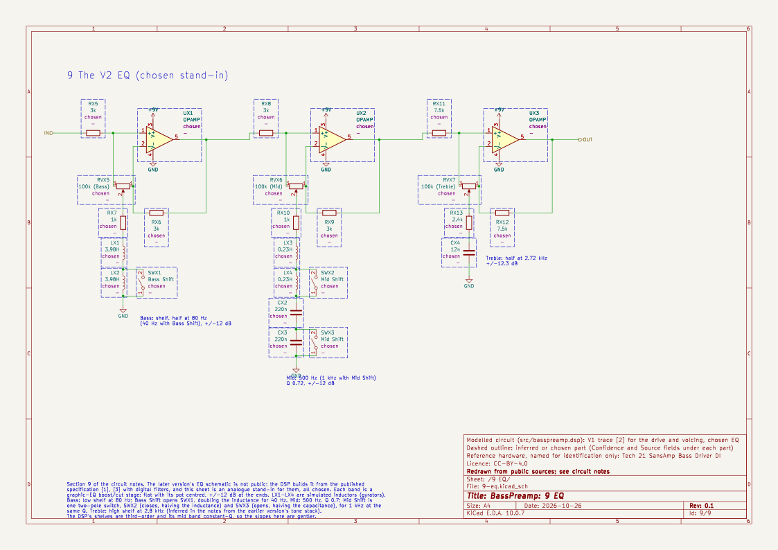
Each stage with component values has a sheet of the KiCad schematic, redrawn from these notes. Sheets 2 to 8 follow the public trace [2] and keep its designators; designators with an X (RX1, RVX1 …) are parts the trace does not name or the notes add, and dashed outlines mark the inferred and chosen ones. It is the circuit BassPreamp implements, not a trace of the V2 pedal.
1. Controls and interface
| Control | Function | Confidence |
|---|---|---|
| LEVEL | Output volume | Documented [1], [3] |
| BLEND | Mix of the clean signal and the preamp ("tube") signal. Fully up is the preamp only. | Documented [1], reported [3] |
| DRIVE | Amount of overdrive | Documented [1] |
| PRESENCE | Upper harmonics and definition. Boost only. | Documented [1], reported [3] |
| BASS | ±12 dB, with a switch selecting 40 Hz or 80 Hz | Documented [1], [3] |
| MID | ±12 dB, with a switch selecting 500 Hz or 1000 Hz | Documented [1], [3] |
| TREBLE | ±12 dB. No frequency is published. | Documented [1], [3] |
- Reported [3]: the EQ keeps working with Blend fully down. Inferred: the EQ sits after the blend, as in the V1 schematic [2].
- Not modelled: the −20 dB pad on the XLR output, the +10 dB boost on the 1/4" output, phantom power and the ground lift. These are output-stage switches with no effect on the tone.
2. Overall topology (V1 schematic, reported [2])
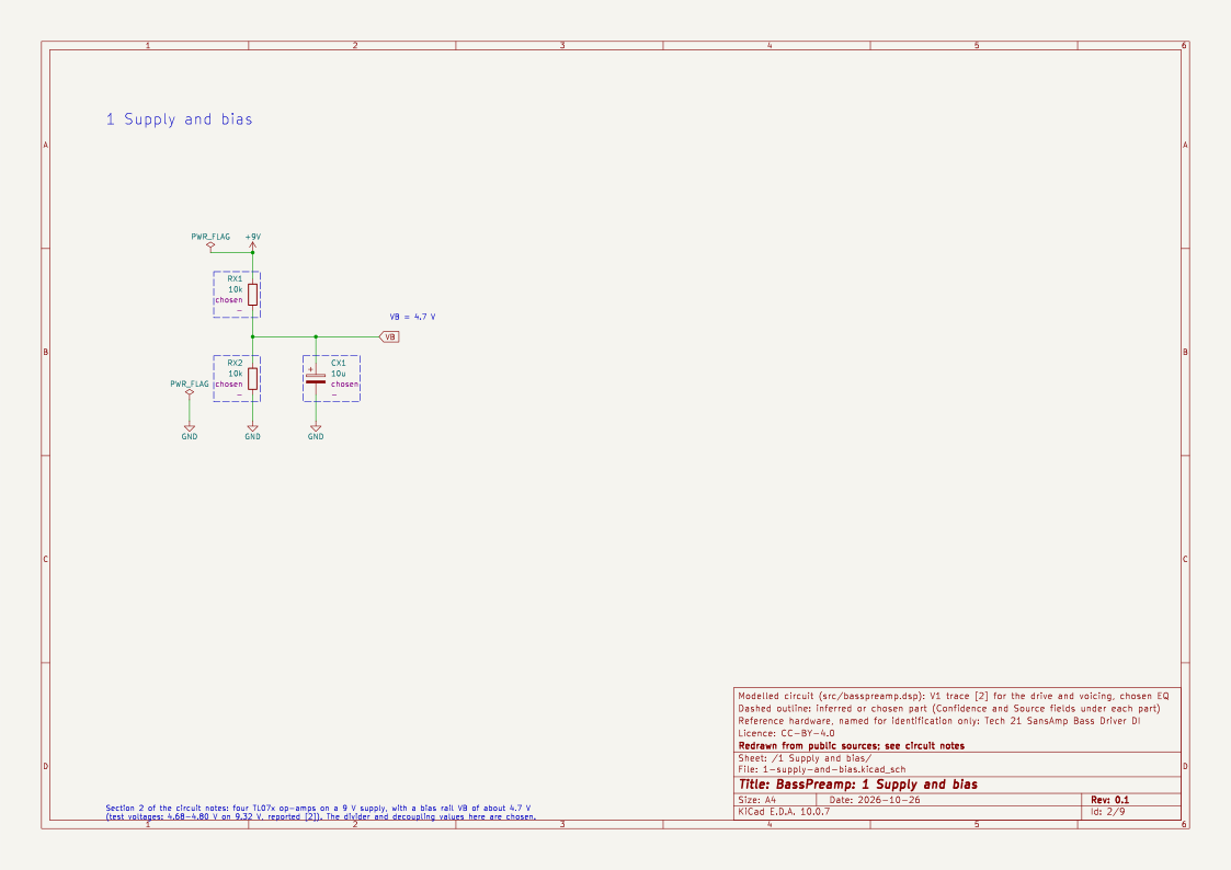
The DIY board [2] is described by its author as "based on" the earlier version. Its schematic has four TL07x op-amps on a 9 V supply with a bias rail VB of about 4.7 V. The published test voltages show VB at 4.68–4.80 V on a 9.32 V supply.
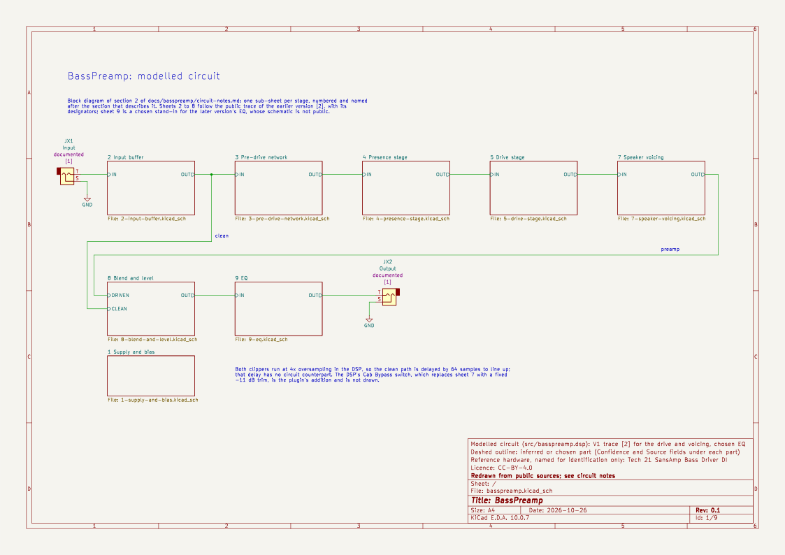
in -> C1 22n / R2 1M -> buffer (IC1_D) -+--------------------------------------- clean --+
                                         |                                                 |
                                         +-> pre-drive network (R3, C2-C5, R4-R6)          |
                                             -> PRESENCE stage (IC2_C)                     Blend pot
                                             -> DRIVE stage (IC2_D)                        (100k B)
                                             -> R11/R12 divider -> Sallen-Key LP + shelf   |
                                             -> Sallen-Key LP (IC2_B)                      |
                                             -> bridged-T notch -> buffer (IC1_A) -> C16 --+
   -> buffer (IC1_C) -> mixer x2.2 (IC1_B) -> LEVEL -> Baxandall bass/treble (IC3_A) -> out
Inferred: the "tube" sound is op-amp clipping in the Presence and Drive stages. The board's author says the same ("It's op-amp clipping which can sound a little ratty" at full Drive) [2]. The "speaker simulation" is the fixed filtering that follows the clipper. It sits only in the preamp path, so the clean side of the blend is full-range.
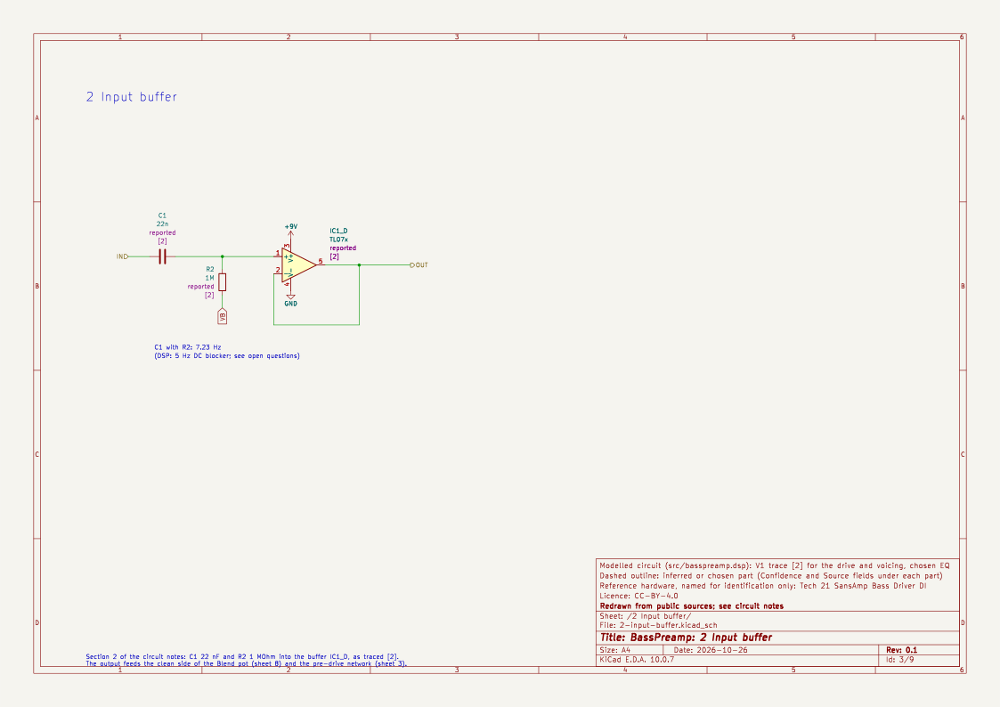
The schematic's root sheet is this block diagram, with one sub-sheet per stage. Sheet 1 holds the 9 V supply and the bias rail VB (divider values chosen), and sheet 2 the traced input coupling and buffer.
3. Pre-drive network (reported values, inferred function)
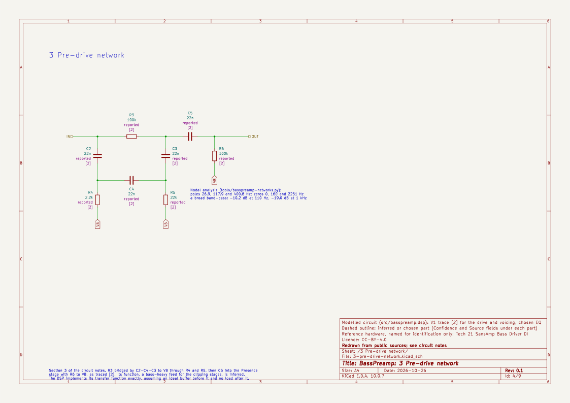
From the buffer, R3 (100 kΩ) runs in series, bridged by C2 and C3 (22 nF each) to two nodes joined by C4 (22 nF), which go to VB through R4 (2.2 kΩ) and R5 (22 kΩ). C5 (22 nF) then couples into the Presence stage's input, with R6 (100 kΩ) to VB.
I solved this network by nodal analysis (tools/basspreamp-networks.py). Its poles are at 26.9, 117.9 and 400.8 Hz, and its zeros at 0, 160 and 2251 Hz. The response is a broad band-pass:
| 41 Hz | 110 Hz | 420 Hz | 1 kHz | 3.3 kHz | 10 kHz |
|---|---|---|---|---|---|
| −10.4 dB | −10.2 dB | −14.1 dB | −19.0 dB | −24.6 dB | −26.0 dB |
So the clipping stages are fed a bass-heavy signal, which is why the drive stays "thick" rather than fizzy.
4. Presence stage (reported values, inferred function)
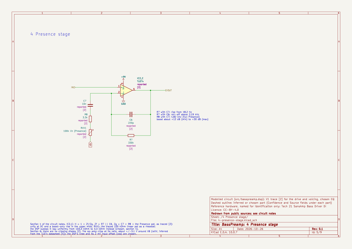
IC2_C is a non-inverting stage:
- feedback: R7 (330 kΩ) in parallel with C6 (220 pF)
- ground leg: C7 (10 nF) in series with R8 (3.3 kΩ) and the PRESENCE pot (100 kΩ linear, wired as a rheostat)
Its gain is
H(s) = 1 + Z_f / Z_g, with Z_f = R7 ∥ C6 and Z_g = R8 + R_pot + 1/(s·C7)
- Unity at DC.
- R7·C7 puts the start of the rise at about 48 Hz, and R7·C6 rolls it off above 2.19 kHz.
- At minimum Presence (R_g = 103 kΩ) the boost is about +12 dB around 1 kHz.
- At maximum Presence (R_g = 3.3 kΩ) the 3.3 kΩ / 10 nF corner (4.8 kHz) is fully engaged, and the boost reaches about +30 dB in the 2–5 kHz range.
- Between those two settings, the boost-only character matches the documentation.
Inferred: this is a gain stage, not just an EQ. With hot input and full Presence, its op-amp can clip too [2] (the author notes oscillation risk with Treble, Presence, Drive and Level all at maximum because of "the cascaded gain stages of the Presence and Drive"). BassPreamp clips it with the same rail model as the Drive stage (section 6).
Chosen: the traced pot is linear, which crowds the audible change into the last part of the rotation. BassPreamp sweeps R_g log-uniformly from 103.3 kΩ to 3.3 kΩ, so equal steps of the control give roughly equal steps in dB. At 50 % this gives R_g ≈ 18.5 kΩ.
5. Drive stage (reported values, inferred function)
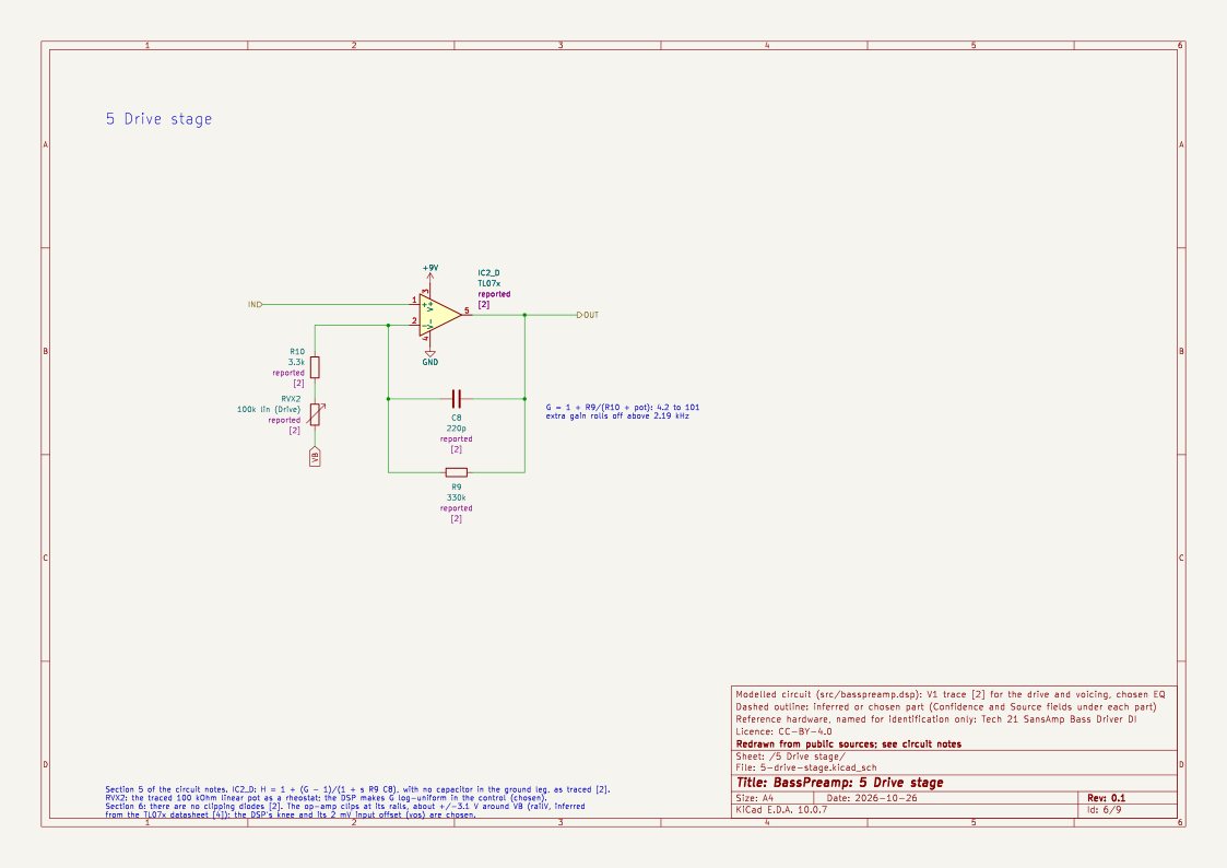
IC2_D is a non-inverting stage:
- feedback: R9 (330 kΩ) in parallel with C8 (220 pF)
- ground leg: R10 (3.3 kΩ) in series with the DRIVE pot (100 kΩ linear, as a rheostat)
There is no capacitor in the ground leg. Its gain is
H(s) = 1 + (G − 1) / (1 + s·R9·C8), G = 1 + R9 / (R10 + R_pot)
G runs from 4.2 (12.5 dB) to 101 (40 dB), and the extra gain rolls off above 2.19 kHz.
- Reported [2]: "The Drive control will bunch up at the very last part of its rotation." With a linear pot, G is only 7.2 at mid-rotation and climbs steeply in the last 20 %, which agrees.
- Chosen: as for Presence, BassPreamp makes G log-uniform in the control: 4.2 at 0 %, 20.6 at 50 % and 101 at 100 %. A reviewer describes noon as the "fat tube" sound and full Drive as fuzzy [3], and this mapping puts audible breakup near noon.
6. Clipping (inferred and chosen)
There are no clipping diodes in the drive path [2]. The nonlinearity is each op-amp running into its supply rails.
- Inferred: a TL07x output swings to about 1.5 V from each rail (datasheet typical [4]). On a 9.3 V supply with VB in the middle, that is about ±3.1 V around VB (
railV). - Chosen: the rail limit is
pk.kneeClip(3.1, 5), a knee that stays nearly linear up to about 2 V and then limits fairly hard. The hardness (railN= 5) is a choice. - Chosen: op-amp clipping is close to symmetric, so it mainly gives odd harmonics. The one asymmetry I model is physical. Because the Drive stage has gain at DC, its input offset voltage is amplified by G and shifts the operating point. I use
vos= 2 mV (the TL07x typical is 3 mV [4]), added before the clip. This gives an H2 that rises with Drive (−61 dBc at 50 %, −35 dBc at 100 % on 41 Hz). The real offset varies from chip to chip, so this is a tuning constant. - Not modelled: the mixer stage (IC1_B, gain 2.2) can also clip when Blend and Drive are both high, since the driven path arrives at about 2 V peak. In a plugin with a digital Level control this would only add an extra, level-dependent clipper, so I left it out (section 8).
Both clippers run at 4x oversampling (pk.oversample4), each around a memoryless rail function, with the linear stages between them at the base rate. The total latency is 2 × 32 = 64 samples.
Measured on single sines at −12 dBFS (preamp path only, Presence 50 %):
| Drive | 41 Hz THD | 41 Hz H2 / H3 | 110 Hz THD | 110 Hz H2 / H3 |
|---|---|---|---|---|
| 0 % | < 0.01 % | — | < 0.01 % | — |
| 50 % | 0.4 % | −61 / −49 dBc | 1.9 % | −54 / −34 dBc |
| 100 % | 18.8 % | −35 / −15 dBc | 8.7 % | −48 / −23 dBc |
The 110 Hz figures are lower than the 41 Hz ones mainly because the post-clip notch near 420 Hz (section 7) removes much of the 3rd to 5th harmonics of 110 Hz.
7. The fixed "speaker" voicing (reported values, inferred function)
After the Drive stage, all of the following are fixed:
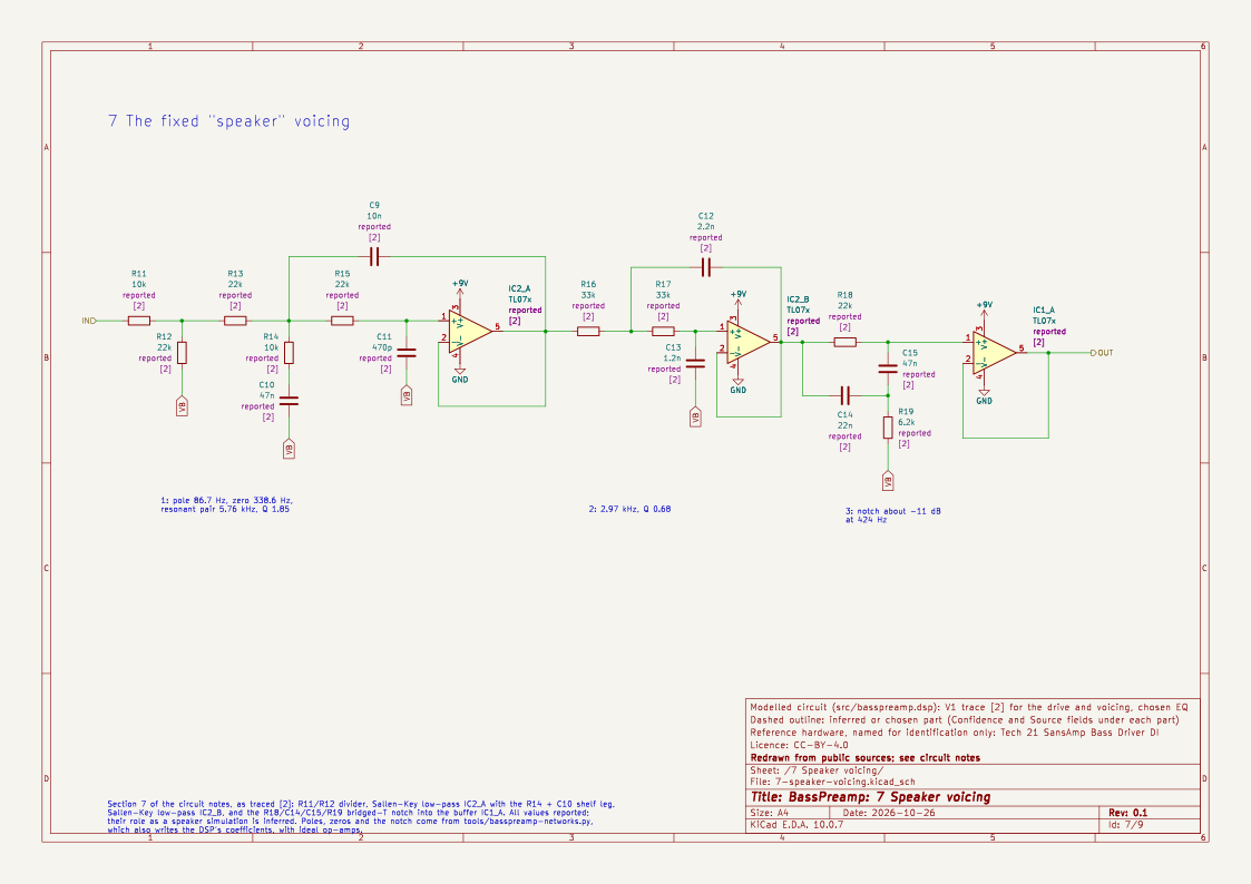
- Divider and first Sallen-Key low-pass (IC2_A). R11 10 kΩ and R12 22 kΩ, then R13 and R15 (22 kΩ), C9 (10 nF) and C11 (470 pF), with a shelf leg R14 (10 kΩ) + C10 (47 nF) at the middle node. Nodal analysis gives a real pole at 86.7 Hz, a zero at 338.6 Hz, and a resonant pair at 5.76 kHz, Q 1.85. The result is a low shelf of about −10 dB above ~200 Hz, a peak around 4–5 kHz, and a steep fall above.
- Second Sallen-Key low-pass (IC2_B). R16 and R17 (33 kΩ), C12 (2.2 nF) and C13 (1.2 nF): 2.97 kHz, Q 0.68.
- Bridged-T notch. R18 (22 kΩ) bridged by C14 (22 nF) and C15 (47 nF), with R19 (6.2 kΩ) to VB: about −11 dB at 424 Hz.
Together these give the preamp path a bass hump around 100 Hz, a dip at 450–500 Hz, a second hump around 1 kHz, and a roll-off of about −57 dB at 12 kHz relative to the peak. This is the "speaker simulation". It is always on, as on the hardware, and applies only to the preamp path. The plugin adds a Cab Bypass switch, which the hardware doesn't have: it replaces these three sections with a fixed trim of −11 dB, chosen so that a plucked bass line keeps the same K-weighted loudness at Drive and Presence 50 % (measured by tests/basspreamp/test_cabsim.py).
All of these coefficients come from tools/basspreamp-networks.py, which takes ideal op-amps and the traced values and prints pk.tf2a/pk.tf1a sections. If a value changes, rerun it.
8. Blend, level and calibration
-
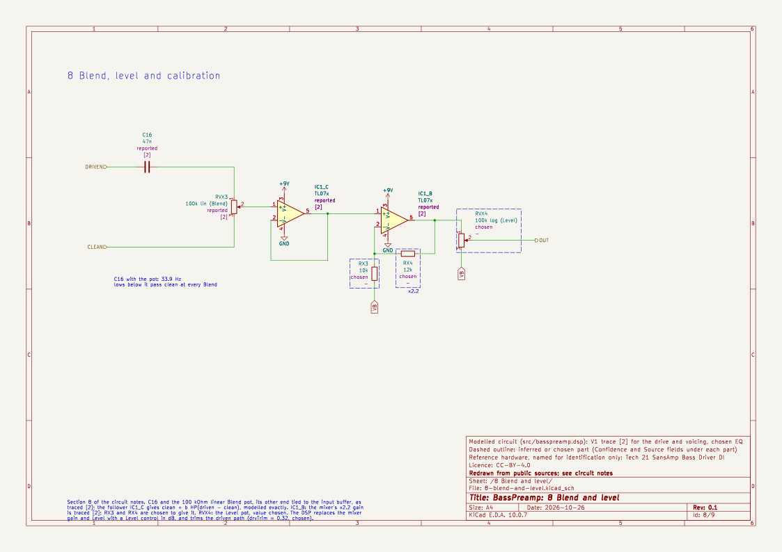
Reported [2]: the preamp path reaches the Blend pot (100 kΩ linear) through C16 (47 nF), and the pot's other end is tied straight to the input buffer. The pot wiper drives a follower, so the wiper voltage is
clean + b · HP(driven − clean), with HP first-order at 1 / (2π · 100 kΩ · 47 nF) ≈ 34 Hz
This is modelled exactly. Below about 34 Hz the clean signal passes at every Blend setting, so a 5-string's low B keeps its fundamental. The clipper's DC offset is removed here too.
- Inferred side effect: at Blend 50 % and high Drive, the clean and phase-shifted driven signals cancel near 2.5 kHz (a notch of about −25 dB). Above the speaker roll-off, a little clean signal (1 − b) remains at every Blend setting below 100 %. A summing blend with this topology would behave the same way on the hardware.
- Chosen: on the hardware, turning Blend up raises the output a lot ("plenty of boost on tap" [2]), because the driven path is several volts. BassPreamp trims the driven path (drvTrim = 0.32) so that a band-limited 55 Hz sawtooth at −12 dBFS has the same RMS level on both paths at Drive and Presence 50 %. The Drive control still changes the level, by about −5 dB at 0 % and +7 dB at 100 %, as on most preamps.
- Chosen: the mixer's ×2.2 gain and the Level pot are replaced by the Level control in dB. 0 dB at Blend 0 with a flat EQ is unity gain.
- Chosen: 1.0 digital full scale is treated as 1 V peak at the input, as in BassDrive. Every Drive setting depends on this, so it is the first thing to check by ear (README).
The schematic draws the traced Blend network and mixer. The mixer's resistors and the Level pot's value are not in the notes, so they are chosen to give the traced ×2.2 gain.
9. The V2 EQ (documented specification, chosen shapes)
The V1 schematic has an inverting Baxandall bass/treble stage (IC3_A) after the Level pot, with C18 (100 nF) coupling into it. The V2 adds a Mid control and the two shift switches, and its schematic is not public. BassPreamp therefore builds the EQ from the specification:
- Bass: a 3rd-order Butterworth low shelf (
fi.low_shelf), ±12 dB, with its corner at 80 Hz, or 40 Hz with Bass Shift. At the corner the boost is about 3 dB short of the full value (measured +9.3 dB at 80 Hz for +12 dB). Whether the hardware uses a shelf or a peak is not documented. A shelf was chosen because the V1 control it grew from is a Baxandall shelf. - Mid: a constant-Q peaking band (
fi.peak_eq_cq), ±12 dB, Q 0.7 (chosen), at 500 Hz, or 1 kHz with Mid Shift. - Treble: a 3rd-order high shelf, ±12 dB, corner at 2.8 kHz. This is inferred from the V1 Baxandall values: the treble capacitors are 10 nF, the treble leg is 3.3 kΩ and the bass-side resistors are 10 kΩ, which puts the turnovers at about 1.6 kHz and 4.8 kHz, with 2.8 kHz between them.
- Shift switches: each switch value is smoothed and glides the corner frequency on a log scale (80 → 40 Hz, 500 Hz → 1 kHz) over a few tens of milliseconds, so flipping it does not click.
- Deliberate difference: 0 dB is flat on all three bands. A real active EQ at noon is close to that, but not exactly. The V1's C18 coupling into the tone stack (a high-pass in the low hundreds of hertz, depending on the Level pot's position) is not modelled, because the V2 extends the bass down to 40 Hz and evidently does not cut there.
With no V2 schematic, the schematic's EQ sheet is an analogue stand-in for the DSP's filters, every part chosen: graphic-EQ boost/cut stages, a series R-L leg for the Bass shelf (Bass Shift opens a switch to double the inductance), a series R-L-C leg for Mid (Mid Shift halves both L and C, keeping Q 0.7), and an R-C leg for the Treble shelf. Its script checks the frequencies, Q and ranges against the values above. Its shelves are first-order where the DSP's are third-order.
Sources
- Manufacturer's description and specification of the V2 (controls, ±12 dB EQ, shift switches), as reproduced on retailer pages: https://www.americanmusical.com/p/tech-21-sansamp-bsdr-v2-bass-driver-di and https://www.thomann.co.uk/tech_21_bass_driver_di_v2.htm
- madbeanpedals, "SludgeHammer24" DIY build document (based on the earlier version): full schematic, bill of materials, test voltages and build notes on the Drive taper, op-amp clipping and the Presence/Drive gain cascade: https://www.madbeanpedals.com/projects/_folders/BassSeries/pdf/SludgeHammer24.pdf
- Bonedo, review of the V2 (control behaviour, EQ ranges and frequencies, Blend and EQ interaction, Drive at noon and at maximum): https://www.bonedo.de/artikel/tech21-sansamp-bass-driver-di-v2-test/3
- Texas Instruments TL07x datasheet (output swing, input offset voltage): https://www.ti.com/product/TL072
- Bass21, an open-source (GPL-3.0) model of the V1. Cited only for its README's statement that a circuit analysis of the V1 is feasible. Its code was not read: https://github.com/jpcima/Bass21
Open questions to settle by ear or with a V2 schematic
- Whether the V2's drive section, Presence and speaker voicing are the same as the V1 trace.
- The V2 EQ's actual topology: shelf or peak for Bass, the Mid Q, and the Treble frequency.
- The real Drive and Presence pot tapers, and whether the original also bunches up.
- How much asymmetry (offset, rail mismatch) a typical unit's clipping has.
- Whether the mixer stage's clipping at high Blend and Drive is part of the sound people expect.
- The input high-pass. The traced C1 (22 nF) into R2 (1 MΩ) gives 7.2 Hz, but the DSP uses a 5 Hz DC blocker at the input. The difference is about 0.1 dB at 31 Hz, but the DSP should follow the trace or the notes should say why not.